
Wednesday, August 17, 2011
Sunday, August 7, 2011
Image Processing with MATLAB (Basic)
In this section: We processing the image with MATLAB code.
We will start with the basic and to make progress to advance level together.
MATLAB: lesson1 "load image to MATLAB"
Getting Start
Don't forget "The file must be in the current directory or on the MATLAB path"
(In this blog Comment are green texts start after %(comment))
FunctionDon't forget "The file must be in the current directory or on the MATLAB path"
(In this blog Comment are green texts start after %(comment))
:imread
Description
:reads a greyscale or color image from the file specified by the string 'filename'
Note: Please download bubbles.jpg to your computer first (ex. E:\Blog)
Example 1
read image
>>M=imread('bubbles.jpg'); %(imread returns the image-file data in the array 'M')
View this image with
>>imshow(M); %(displays the intensity image M)
or
>>imview(M); %(displays the intensity image M)
like this Fig.


Example 2
read image sequence
download This File to your computer first
(this contain image01.tif-image05.tif & Read_image_Series.m)
%%%%%%%%%%
clear all
b = 1; %(first image)
npic = 5; %( last image)
for i=b:npic;
str = num2str(i); %(convert number 'i' to string)
name = strcat('','image0',str,'.tif'); %(('','image0',str,'.tif') :''=directory contain file.'image0'=incomplete file name. str = string mean that 1.'.tif'= file format all of this mean that name is image0str.tif=image01.tif)
MAT = imread(name);
figure() %( reserve figure)
imshow(name); %(display image name)
title(i); %( show title in each image with the no.)
end
%%%%%%%%%%
Function
:aviread
Description
:Read an Audio/Video Interleaved (AVI) file
Example 3read avi file
download avi file to your computer
%%%%%%%%%%
>>Ar=aviread('movie01.avi');
Example 4make avi file
download Image Series to your computer%%%%%%%%%%
clear all
b = 16;
npic = 60;
mov = avifile('MakeVi01.avi') %MakeVi01.avi name of avi-file save to your comp.
for i=b:npic;
str = num2str(i);
name = strcat('ImageSe/','SPT200',str,'.tif'); % ex. image1.tiff : (file name= 'SPT200')
MAT = imread(name);
imshow(MAT);
axis off;
title(i);
F(i) = getframe(gca);
mov = addframe(mov,F(i));
end
mov = close(mov)
=============================================================
MATLAB: lesson2"Filtering in MATLAB"
Function
:Y= filter2(filter,image,shape)
Description
:returns the part of Y specified by the shape parameter. shape is a string
with one of these values:
'full' Returns the full two-dimensional correlation. In this case, Y is larger than X.
'same' (default) Returns the central part of the correlation. In this case, Y is the same size as X.
'valid' Returns only those parts of the correlation that are computed without zero-padded edges. In this case, Y is smaller than X
Example 1download file
%%%%%%%%%%
>> clear all
>> a=imread('cute01.tif');
>> imshow(a);
>> Fil=fspecial('average');% function fspecial is one(3,3)/9
>> aFilter=filter2(Fil,a);
>> imshow(aFilter/255);


Image Series
Saturday, August 6, 2011
Sherlock Holmes 2 : A Game of Shadows trailor
Sherlock Holmes 2: A Game of Shadows Trailer 2011 HD
In theaters: December 16th, 2011
Genre: Action and Adventure, Thriller
Official Site: http://www.sherlockholmes2.com
Director: Guy Ritchie
Cast: Robert Downey Jr., Jude Law, Noomi Rapace, Jared Harris, Eddie Marsan, Stephen Fry, Gilles Lellouche
Writers: Kieran Mulroney, Michele Mulroney
Storyline:
Sherlock Holmes and his sidekick Dr. Watson join forces to outwit and bring down their fiercest adversary, Professor Moriarty.
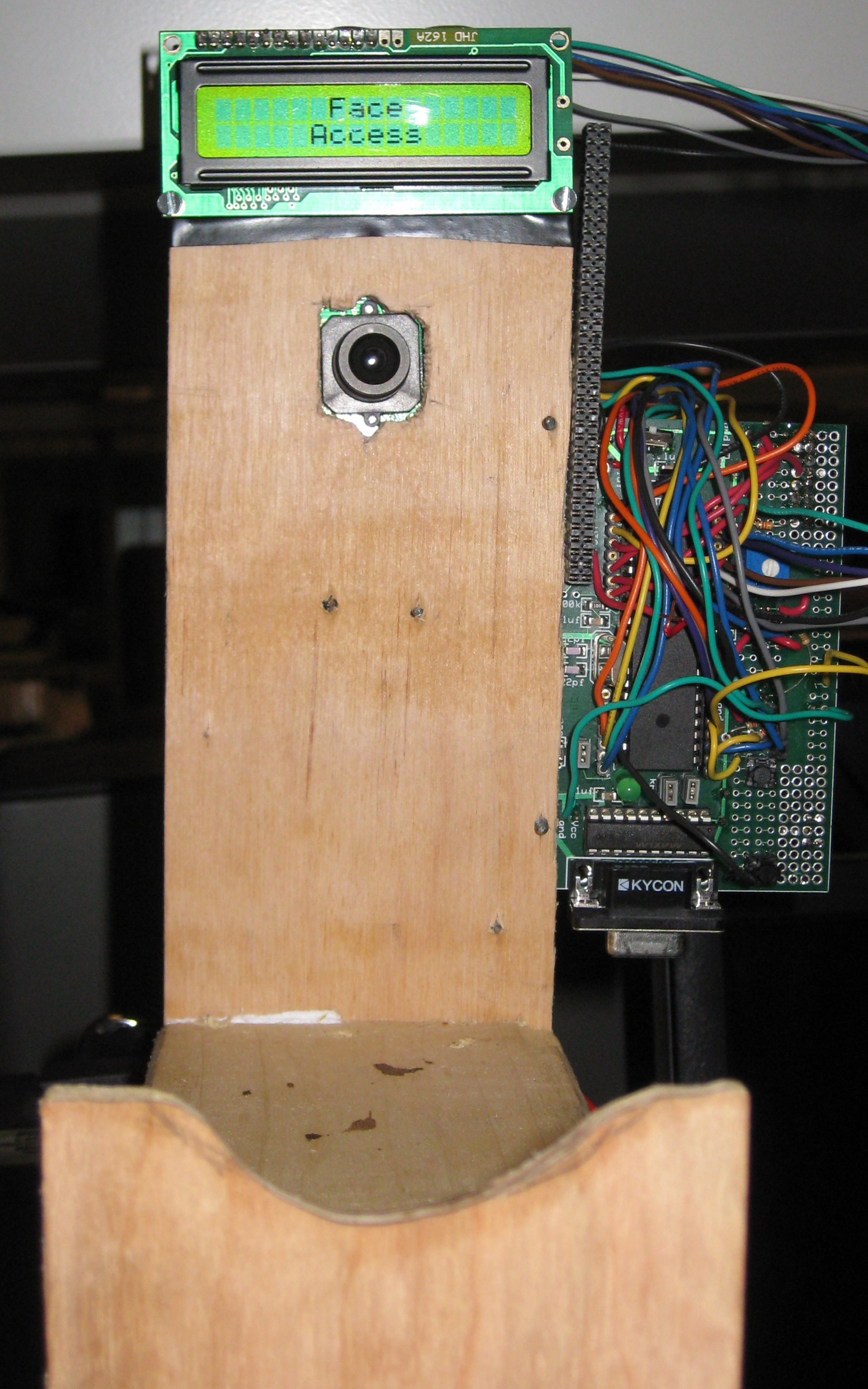
Face Access : A Portable Face Recognition System
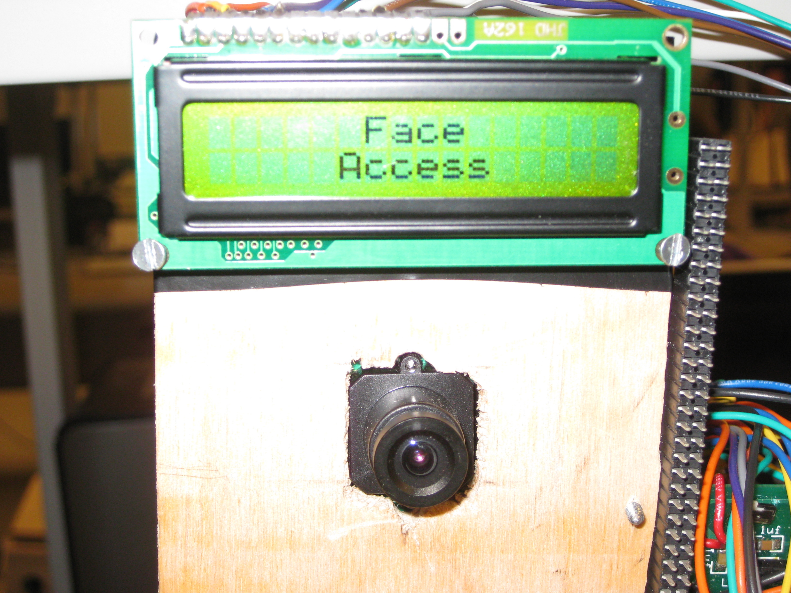
"A standalone face recognition access control system"
project soundbyte
We created a standalone face recognition system for access control. Users enroll in the system with the push of a button and can then log in with a different button. Face recognition uses an eigenface method. Initial testing indicates an 88% successful login rate with no false positives.
There are currently commercially available systems for face recognition, but they are bulky, expensive, and proprietary. Our goal was to create a portable low-cost system. Our design consists of an Atmel ATmega644 8-bit microcontroller, a C3088 camera module with an OmniVision OV6620 CMOS image sensor, Atmel's AT45DB321D Serial Dataflash, a Varitronix MDLS16264 LCD module for output, a 9-volt battery, and a small wooden structure for chin support.
High Level Design
Our design is split into three different processes: training, enrolling, and logging in.
Training
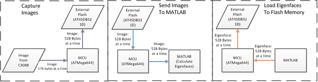
The training process is the only time we use a computer; once this step is complete, the system is completely standalone. If we were to sell this system as a consumer product, we would ship the system pre-trained. The training process consists of teaching the system to key in on the most important features of a face. To do this, a large number of facial images are taken and sent to Matlab to help the system determine the distinguishing features of a face. We use Matlab to create the eigenfaces, which are the principle components of the training set (See Principal Component Analysis). Because the images were too large to be held on the microcontroller, we captured an image a line at a time, sending each line to flash before the camera sends the next line. We then send the image through the microcontroller to Matlab over the serial port. Once all of the training images are in Matlab the eigenfaces and average face are created (see Background Math for more information). Finally, the eigenfaces and average face are sent to flash memory through the microcontroller. Once the eigenfaces and average face are in flash, the system is completely standalone.
Enrolling
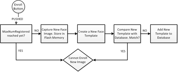
Before a user can login to the system, he first needs to register his face and enroll it into the database. To enroll into the system, the user presses the enroll button, which will capture the image. Before the image is captured, the current number of system users is checked; if the maximum number of users is met the new user cannot be enrolled. We set our maximum to 20 users. If the maximum hasn't been met, the user's face image is captured and is once again sent to flash memory 176 bytes at a time (same as in the training process) and is stored there temporarily for calculation. The image and eigenfaces are all pulled back to the microcontroller 528 bytes at a time to calculate the new user's "template", which is a short vector describing the user's correlation with the eigenfaces. (see Background Math for more information). The template is then compared with the previously stored templates; if the new template is too close to a previous template, the user cannot be enrolled. We defined the "closeness" between two templates as the cosine of the angle between them. If there are no matches, the new template is added to the database in flash memory to save it in case of a system reset.
Logging in
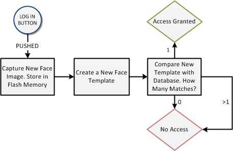
The Logging In process is initially very similar to enrolling. The user presses the login button to take his picture, store it in flash memory and begin the logging in process. Again the newly captured image and eigenfaces are pulled from flash back to the micrcontroller 528 bytes at a time to calculate the user's template. This template is compared with all of the previous templates. For the user to be logged in, their template needs to "match" (be close enough to) only one saved template; otherwise they will be "denied access". Again, the cosine of the angle between the two templates is used to determine template match. Whether or not the user was logged in, the top three matches are displayed on the LCD.
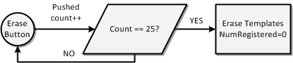
Erasing Users
We currently only have the system setup to have up to 20 enrolled users. However, for demo purposes we wanted the ability to enroll new users and erase the old ones. To do this we added a final button on the back of our protoboard for this purpose. The button needs to be held down for an entire second before the function to erase templates is called. A message is displayed to the LCD to let the user know that the enrollments have been erased.
Standards Used
For communicating with flash memory we used the Serial Peripheral Interface (SPI). For programming the camera we used the Inter-Integrated Circuit (I2C) interface. The video signal was digital, so it was not NTSC, but understanding the NTSC standard helped us understand the camera output.
Intellectual Property
The eigenface method is in the literature, so we have no intellectual property concerns. We plan to try to publish our results, so we are fully disclosing our design.
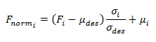
Background Math
When one thinks of face recognition, one immediately thinks of finding features of a face: eyes, nose, ears, cheek bones. But who's to say that these are the most distinguishing characteristics of a face, and that they are the best features by which a face should be described? And what if these features are correlated? Instead of hard-coding features for detection, we decided to find the orthogonal features that most optimally describe our large training set by using Principal Component Analysis. This creates an orthogonal basis of principal components for our training set. The basis vectors are known as eigenfaces, and can be thought of as characteristic features of a face. All new faces will be described as a linear combination of these eigenfaces. This is equivalent to projecting the new face onto the subspace spanned by our eigenfaces. By using only the eigenfaces with the highest eigenvalues, we ensure that our projection maintains the most face-like energy from the image. This method was proposed by M. Turk and A. Pentland in 1991.
The system is divided into three different processes: Training, Enrolling, Recognizing.
Training
The training portion of the system consists of creating the eigenfaces based on a set of training faces. The goal was to create as many eigenfaces as possible and keep the M eigenfaces that had the highest eigenvalues.
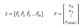
Given N training images, create a matrix where each column is a face vector of length 176 * 143 = 25168.
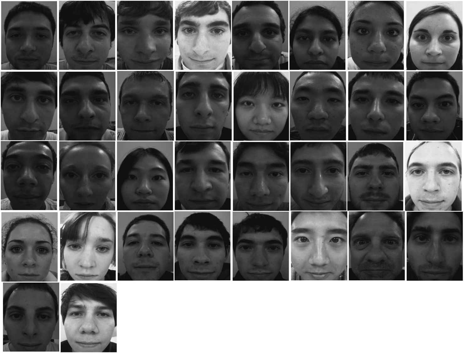
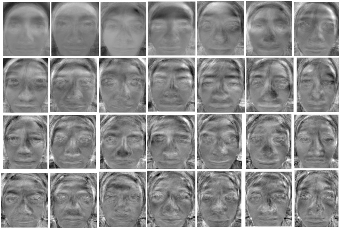
We used a total of N=40 training faces to create the eigenfaces. Below are the raw images captured (before any processing) of some of our volunteers; not all of these faces were used to create the eigenfaces.
To create the eigenfaces we use the following algorithm:
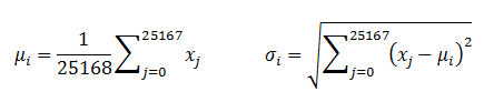
- Normalize each face
- Calculate the mean and standard deviation of each face. This is like brightness and contrast.
- Normalize each image so that each face is closer to some desired mean and standard deviation
- Calculate the mean image based on the M normalized images.
- Calculate the difference matrix using the new mean face.
- Find the eigenvectors of D * D'. However, this is too large of a matrix so it can not be done directly.
- Find the eigenvectors v of D' * D.
- Multiply the resulting eigenvector by D to get the eigenvectors of D * D'.
- Take the eigenfaces that correspond to the M eigenvectors with the highest value.

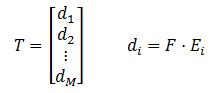
Below are 28 of the 30 eigenfaces we created. For enrolling purposes we use only the top 25 eigenfaces.
Enrolling
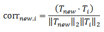
The enrollment process consists of creating a user "template" for comparison when he tries to log in again later. The template is an M-length vector (M is the number of eigenfaces used to create the face space) that represents the correlation of the user's face with each eigenface. We use M = 25.
To create a user template from the 176x143 face image, we use the following algorithm:
- Follow the same steps as above to normalize the new face image to the desired mean and standard deviation used in the eigenface calculation.
- Create the "difference" face by subtracting the average face from the normalized new face
- Dot the "difference" face with each eigenface. The value of the ith dot product is the ith element of the template. T is the template, F is the difference face, and E is the eigenface.
Logging In
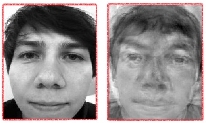
When a user attempts to log in, a new face template is created from the newly captured image as described above. This template is then compared with every other saved template. The measure of correlation we use is the cosine of the angle between the different templates. If the correlation between two templates is above the desired threshold then a "match" has been found. After testing, we decided to use 0.85 as a threshold. This was small enough to reduce false negatives while high enough to eliminate false positives.
To log in a user with their new 176x143 image, we used the following algorithm:
- Follow the same steps as the enrollment process to create a new template, T_new
- Calculate the correlation of T_new with all of the stored templates to find the number of matches.
Below is a visual example of the projection of a face onto our eigenface space. The image on the left is the image captured by the C3088 camera, and the image on the right is the reconstructed linear combination of eigenfaces defined by the user's template. This person was not used to create the eigenfaces. We never actually create this reconstructed image on the microcontroller. We only store the template.
Hardware and Software
Circuit Board attached to wooden structure
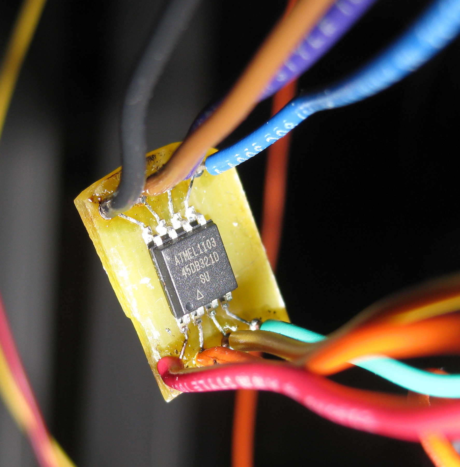
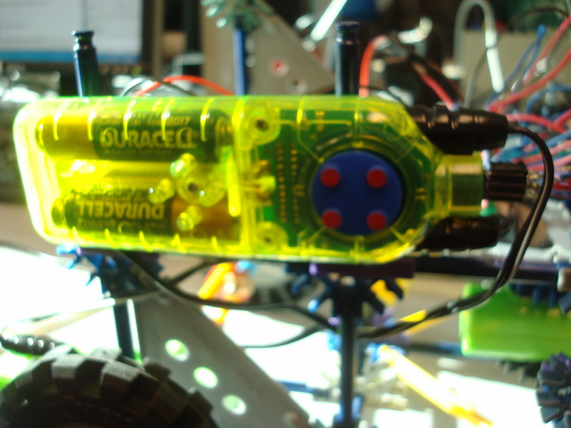
Atmel At45DB321D Flash Memory
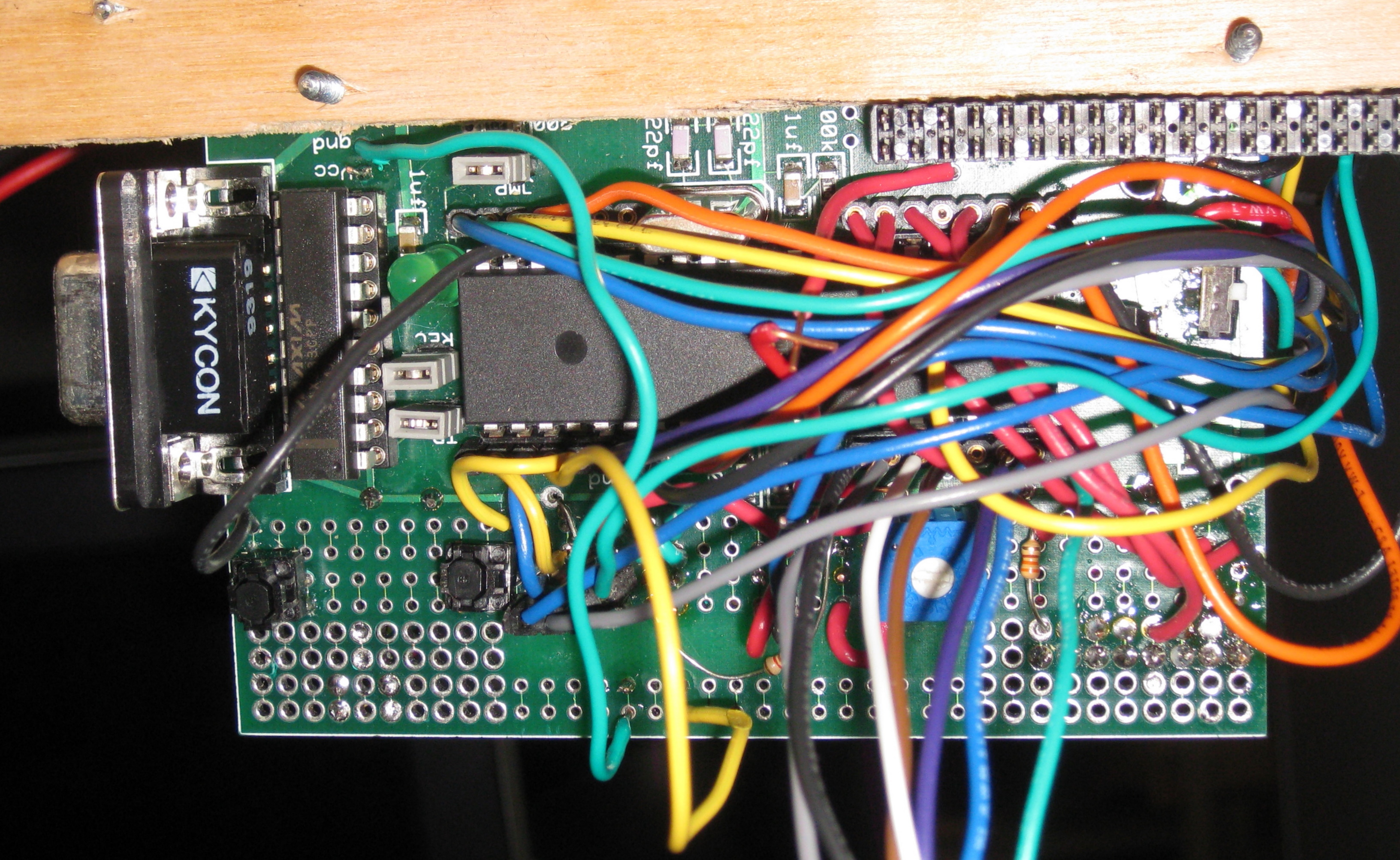
We fastened all of our hardware together for portability. A wooden structure with a chin plate is used to hold the camera in place and to normalize the position of a user's face during image capture. An LCD is fixed to the top of the wooden structure to provide system feedback to the user. A printed circuit board connects all of the electronic components including the microcontroller, flash memory, and all three buttons. The board layout was designed by Bruce Land for ECE 4760. We reused the board from a previous group. The board is attached to the side of the wooden structure so the user can easily find and press all of the buttons.
Flash Memory and the Serial Peripheral Interface (SPI)
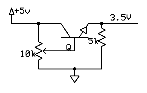
The ATmega644 only has 4 kB of RAM. This is not enough to hold even one 176x143 image. We need to store a possible 50 images for the eigenfaces. For external memory, we use the AT45DB321D serial dataflash from Atmel. It stores 2 MB in 4096 pages of 528 bytes per page. This chip requires a Vcc of 2.5 - 3.6V. We chose 3.5V so that logic high from the flash would be read as logic high on the microcontroller, which has a Vcc of 5V. We used the voltage regulator circuit to the right to supply 3.5V to flash.
In addition to main memory, the chip has two 528-byte buffers. You can read from buffers or main memory. To write main memory, you must first write to a buffer, and then copy the buffer to main memory. The latter is an internally timed operation which takes about 3 ms. The speed of the former depends on how much data you clock into the buffer and at what rate.
Communication with flash memory uses the Serial Peripheral Interface (SPI), which is a full duplex serial communication protocol. The ATmega644 has dedicated SPI hardware which makes coding easy. We configured the microcontroller as the master and flash as the slave. The microcontroller outputs a clock on pin B.7 to flash through a 1k resistor. The microcontroller outputs data on pin B.5 to flash through a 1k resistor. Flash outputs data to the microcontroller on pin B.6 through a 330 ohm resistor. Chip select is pin B.3. Brian wrote a general purpose library called flashmem.c for communicating with flash. A description of its functions is below.
- void spi_init(): Configures the microcontroller SPI parameters.
- unsigned char readStatusRegister(): Returns the contents of the flash’s status register.
- unsigned char isBusy(): Returns the most significant bit of the flash’s status register. The assertion of this bit indicates the flash is busy.
- void writeBuffer(unsigned char data[], unsigned int n, unsigned int byte, char bufferNum): Writes the first n bytes in the data array to buffer 1 or 2, depending on bufferNum. The data will be copied to locations [byte : byte+n-1] in the buffer.
- void readBuffer(unsigned char* data, unsigned int n, unsigned int byte, char bufferNum): Reads bytes [byte : byte+n-1] in the buffer and copies it into the data array.
- void bufferToMemory(unsigned int page, char bufferNum, char erase): Copies the data in the buffer to a page in main memory. If erase==0, this page must have been previously erased for this operation to work. After this command is sent, the flash will be busy for about 2.5 ms. If erase==1, this function will first erase the page, and then copy the data. This will take about 25 ms.
- void readFlash(unsigned char* data, unsigned int n, unsigned int page, unsigned int byte): Reads bytes [byte:byte+n-1] at the page specified in main memory. The result is copied into the specified data buffer.
- void eraseBlock(unsigned int block): Erases pages [8*block : 8*block+7] in main memory.
- void eraseFace(unsigned char k): Erases blocks [8*k : 8*k+7] in main memory.
Memory Layout
For indexing ease, we thought of main memory in terms of "faces" of 64 pages each. We were having some issues with pages and blocks of pages being randomly corrupted and erased, so we needed to move around the eigenfaces from their original pages in memory. Currently, Face 51 is used as the temporary space for the newly captured image. This face is erased immediately after the user's template has been created and analyzed. Faces 7 through 36 are used to hold the eigenfaces, not in value of importance. There is an index array in the final FaceRecSystem.c to index correctly into these eigenfaces. Finally, the Mean Face is stored in face 37.
Camera Module and the Inter-Integrated Circuit (I2C) Interface
We used the C3088 camera module for image capture. This module uses OmniVision’s OV6620 CMOS image sensor. Camera settings are programmable through a standard Inter-Integrated Circuit (I2C) interface, which is a two-wire, half duplex interface. The camera outputs VSYNC, HREF, and PCLK control signals and an 8-bit parallel digital video output Y7-Y0.
I2C Interface
As with SPI, the ATmega644 has dedicated hardware for I2C. We used an I2C library written by Peter Fleury to create two general purpose functions for the C3088:
- unsigned char camera_read(unsigned char regNum): Returns the contents of the camera register regNum
- void camera_write(unsigned char regNum, unsigned char data): Writes data to the camera register regNum
We mostly used default settings for the camera. Apart from the default settings, we chose to:
- Reduce frame size from 352x288 pixels to 176x144 pixels.
- Reduce frame rate from 60 frames per second (fps) down to about 5 fps.
Video Signal
The OV6620 image sensor outputs an 8-bit parallel gray-scale digital video signal on pins Y7-Y0. It also outputs PCLK, VSYNC, and HREF for timing. The format is similar to the analog NTSC standard. See the timing diagram below. PCLK is a 300 kHz clock. A 4 millisecond (ms) pulse on VSYNC indicates the start of a new frame. After this, data is output row by row. Every row, HREF goes high and data is subsequently sent out on Y7-Y0, one pixel per rising edge of PCLK. HREF is high for about 0.6 ms, during which time 176 pixels are clocked out. HREF is then low for about 1.4 ms before starting the next row.
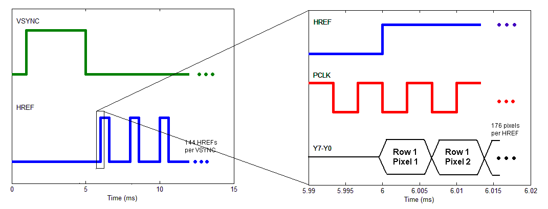
Image Capture
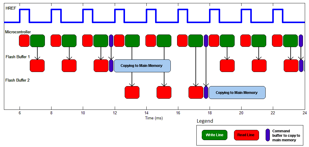
One of the biggest technical hurdles at the beginning of the project was image capture. The ATmega644 only has 4kB of RAM, and a 176x143 pixel gray-scale image is over 25 kB. Thus we were forced to read the video signal and write it to flash simultaneously. To achieve this, we ingest one line (176 pixels) from the camera when HREF is high, and then write it to the flash buffer when HREF is low. Writing a line to the buffer takes about 0.9 ms. Every 3 lines, the flash buffer fills up and we command flash to copy the buffer to main memory. This is an internally timed operation which takes about 3 ms. By alternating buffers every 3 lines, we are able to keep up with the video signal. See the timing diagram below.
Interfacing and Testing with Matlab
We decided that the best way to view the images captured by the camera was to send the captured image from flash memory to Matlab. The easiest way to communicate with Matlab is to use the serial port and the uart as defined by Joerg Wunsch in uart.c and uart.h.
Interfacing with Matlab proved to be a little more complicated than we originally expected because of the amount of data we were trying to transfer at once. The SerialConnect.m Matlab file was split into three separate sections: setting up the connection, receiving data, sending data. The serial connection was setup based on the COM port the microcontroller was connected to as well as the desired baud rate (which must match definition in uart.c). The receive portion of the script is based on receiving chunks of data 66 elements at a time or 528 bytes; we found that this is the maximum amount of data that could be sent to Matlab over the uart in one buffer. The send portion of the script prints to the uart the number of "faces" it is sending, where in flash memory the data is supposed to go, and then the data is sent one byte at a time. We found that if we sent more than one byte at a time and didn't pause in between print statements the microcontroller wasn't able to read in. This unfortunately slowed down flash programming significantly. It took about 3 hours to load all the eigenfaces onto flash.
A MatlabLib.c file was also written to set up the data transfer on the microcontroller side. It was also split up into three different functions. The first is a set of print statements that sets up Matlab's read program to expect the correct amount of data depending on the number of faces and the size of each face being sent over the uart. Another function called dumpFrame() splits up the data and sends it over the uart in blocks of 66. The final function, called readFrame() scans for the amount of data that is being sent over the uart and then does individual scans until it reads all of the data.
These two uart interfaces were used in many of the different processes of the project to move data back and forth between the camera, flash memory, and Matlab. In addition to being necessary to calculate the eigenfaces and send them to flash, this was a very useful debugging tool. There are a number of functions throughout the different C files that use the interface to send data.
- sendFacetoMatlab(unsigned char face): read face 'face' from flash a page at a time and sends it over to Matlab. WE specifically used this to send test images from the camera and previous writes into Matlab to check their correctness.
- pageMatlabFlash(int pagNum): reads one page from Matlab and sends it to page pagNum in flash Memory.
- faceMatlabFlash(char face): sets up the page numbers for a specific face so that pageMatlabFlash can send and receive the correct data to flash memory.
Problems
Our biggest problem was that every so often, our eigenfaces would get corrupted in flash memory. At first we suspected ESD, so we covered flash in an ESD-free bag when transporting our device. We also suspected faulty wiring, so we re-soldered flash, simplifying the wiring and eliminating loopy wires. We also slowed down SPI by a factor of 2. Perhaps some of these things helped since we haven't seen any more corruption, but we have also begun to handle flash with more care, so it is not clear what the problem was.
Results
Accuracy
We tested our face recognition system on 12 people. We conducted 25 normal login attempts, 22 of which were successful. The three unsuccessful login attempts (i.e. false rejections) were barely under the threshold for acceptance. There were zero false acceptances. This was a strict design constraint. A physical access system can have a 10% false rejection rate but should never recognize user A as user B. False rejections are resolved by trying again, but false acceptances usually mean a security breach. Selected test results are below.
We also conducted 10 login attempts with added variables to test the limitations of our design. Such variables included hair modification, glasses, smiling, sticking out tongue, head tilting, etc. We found that our system was sensitive to hair, head tilt, and glasses, but not as sensitive to smiling or sticking out tongue. Selected test results are discussed below.
User 7 Normal Login
The plot below shows 11 login attempts by User 7. In all 11 trials, User 7 correlates most closely with herself. Nine of these logins were correlated enough to be successful. Two were just under the threshold. In her last login attempt User 7 was sticking out her tongue, but her correlation was still above the threshold.
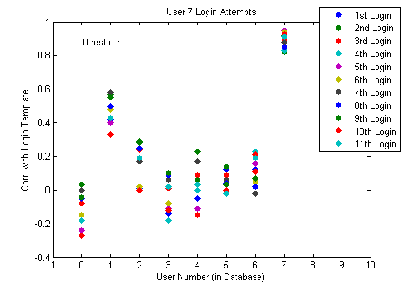
Login Attempts by User 7
User 7 Login with Hair Modification
The plot below displays a limitation of our design. Our system is sensitive to hair arrangment. The plot shows 4 more login attempts by User 7, but this time she let her hair down before trying to log in. Her template in the database was created with her hair pulled back. Letting her hair down brings her correlation well below the threshold.
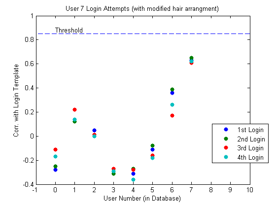
Login Attempts by User 7 with her hair let down
User 8 Normal Login
The plot below shows 5 login attempts by User 8. Four were successful. We suspect that the failed login (attempt 3) was due to User 8 slightly tilting his head during image capture. This is indicative of a limitation of our design. Our system is sensitive to changes in head orientation in both pitch and roll. If we had time, we would have expanded our structure to include a place to rest the forehead. In Login Attempt 5, User 8 was smiling, but the systems still recognized him.
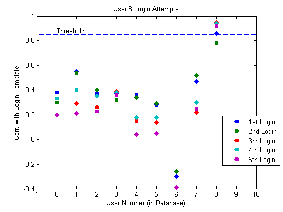
Login Attempts by User 8
Glasses
User 11 enrolled with his glasses on and then failed to log in with his glasses on in three login attempts. The correlation was around 0.60. He removed his glasses and re-enrolled. After this, he could log in (without his glasses) repeatably. This indicates that our system is very sensitive to glasses. This makes sense since none of our training images included glasses. Our face space was chosen to exclude glasses features, so the projection onto the face space of a face with glasses is rather sensitive.
No Face
We performed three tests where we took pictures of non-face objects: hand, water bottle, and background only. In all of these tests, login was unsuccessful.
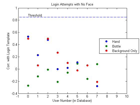
Login Attempts with no face in the picture
Speed
At the beginning of our project we identified run time as a potential problem. The major contribution to run time is calculating the unknown user template. A template is really 25 dot products, one for each eigenface. Each is a length 25168 dot product. This is 630,000 multiplies. In addition to this, we need to load all the eigenfaces from flash to the microcontroller over SPI running at about 100 kB/s. By doing integer multiplications instead of floating point, we were able to bring the run time down to about 15 seconds.
Safety
There are only two possible safety concerns in our design. One is that we ask you to touch your chin to the chin plate. There is a possibility of spreading germs. In a real system, we would probably make this plastic instead of wood, and provide disinfectant to clean the chin plate. The other possible safety concern is that we have some sharp exposed ends of screws. They are not near buttons, the chin plate, or places where you would grab our device to move it.
Usability
Given more time, we would have tried to find more optimizations to reduce runtime. That being said, 15 seconds is a reasonable time for an access control system.
You only need to keep your chin on the chin plate while the image is being captured. This is less than a second. We found that people were confused about this because they couldn't see the LED. The LED is on and only on during image capture. Given more time, we would move the LED to a more visible location.
Since we have a portable system, it can conform to people of all sizes.
Conclusions
Results vs. Expectations
Our results were better than we expected. We were able to show a reasonable login success rate (88%) with reasonable run time (15 seconds). For this we were extremely satisfied. It was a little disappointing that our system was so sensitive to hair modifications, head tilt, and other sometimes unidentifiable variables. Some of these are limitations of the eigenface method.
If we were to repeat this project from scratch, we would do a few things differently. First, we would improve mechanical structure to include a forehead rest or some other head position normalizer. Second, we would use something other than serial dataflash. This could improve run time and would have prevented the data corruptions that plagued our last week. If we improved run time, we could use more eigenfaces, further improving our successful login rate and making our system more robust. We would have also liked to use more training faces, but it was difficult to find more than 50 people in a few days to train our system with.
Conforming to Standards
We were able to communicate with flash memory and with the camera. This means that we successfully conformed to the SPI and I2C standards.
Intellectual Property
Our design poses no intellectual property problems. The eigenface method is well known in the literature. All aspects of our design that we didn't develop ourselves are properly cited in our references below.
We will try to publish our design so everything we did will be in the public domain.
Ethical Considerations
We strived to abide by the IEEE Code of Ethics during this project.
Facial recognition brings up a number of ethical issues. For many people, the mere idea of automatic facial recognition hints at George Orwell’s “Big Brother is watching you.” However, we do not see any ethical issues for our project since all participants are willing and there is no passive recognition. That is to say that no one is being recognized against their will, and every instance of recognition is initiated by the user. It’s not as if we are creating a real-time video facial recognition system using a large public database. No user can be recognized without first registering.
Another concern with many biometric systems is that the biometric template is stored in a database that could be compromised. Even though the captured picture is stored in flash during enrolling and logging in, it is erased as soon as the template is created. It is only stored in flash memory for 15 seconds. The templates themselves do not store the actual face, and the problem of recreating the face from the template and the eigenfaces is underdetermined and cannot be solved. These measures protect the user's identity from a data compromise.
Legal Considerations
Our project is a simple standalone device. It does not emit any appreciable EMF radiation and does not cause interference with other electronics. We made sure to get everyone's permission before publishing their names or images on this website.
Appendices
A. Source Code
Source files
- FaceRecSystem.c (19KB) – the code for enrolling and logging in users using the flow diagrams from the project overview.
- camToMatlab.c (5KB) – the code used to take images, and transfer them from flash memory to Matlab. Used to load training images to Matlab through the serial port.
- MemToMatlab.c (5KB) – the code used to test sending data from flash memory to Matlab through the serial port.
- MatlabToMicro.c (6KB) – the code to move the eigenfaces from Matlab through the microcontroller to the flash memory through the serial port.
The following source files are the libraries we created or borrowed for the project.
- camlib.c (4KB) – the library for setting up the camera and interfacing with it, written by Brian Harding
- flashmem.c (8KB) – the library that sets up the flash memory and controls the reads, writes, and erases, written by Brian Harding
- Matlablib.c (2KB) – the library that sets up the data to be sent to and from Matlab, written by Cat Jubinski
- uart.c (4KB) – an implementation of UART, written by Joerg Wunsch.
- twimaster.c (6KB) – the I2C master library, written by Peter Fleury
- lcd_lib.c (9KB) – the library for the LCD, written by Scienceprog.com
Header files
- camlib.h– written by Brian Harding
- flashmem.h– written by Brian Harding
- MatlabLib.h– written by Cat Jubinski
- uart.h – written by Joerg Wunsch
- i2cmaster.h – written by Peter Fleury
- lcd_lib.h – written by Scienceprog.com
Matlab scripts
- SerialConnect.m (3KB) – used to receive face images from flash memory and send eigenfaces back to flash memory. Written by Cat Jubinski
- getEigFaces.m (6 KB) – used to create the eigenfaces and simulate enrollments and logins in MATLAB. Written by Brian Harding
- efaces0501.mat (592 KB) – Eigenfaces used in the system.
- meanface0501.mat (12 KB) – Mean Face used in the system
Download all files: Code.zip (44KB)
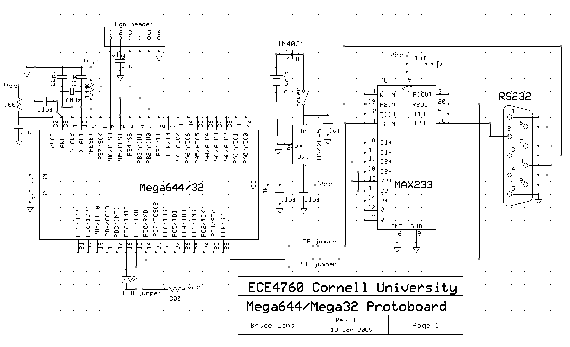
B. Schematics
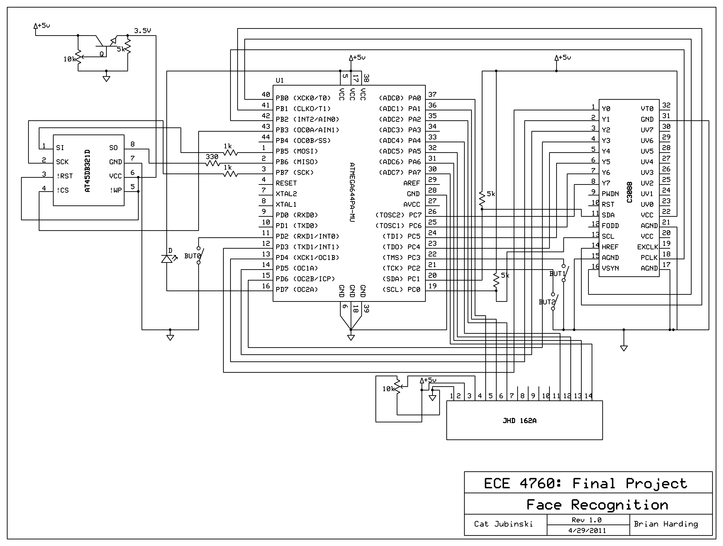
Hardware schematic [full-size image]. Download schematic file: faceAccess_schematics.sch (36KB).
D. Tasks
This list shows specific tasks carried out by individual group members. Everything else was done together.
Brian
- Interfacing with Flash Memory (SPI)
- Programming the Camera (I2C)
- Building Mechanical Structure
- Soldering the PCB
Cat
- Sending Training Images to Matlab
- Sending Eigenfaces to Flash
- Designing Website
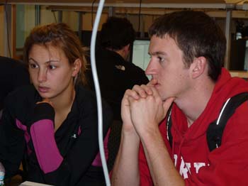
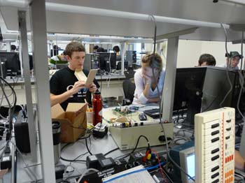
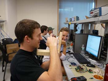
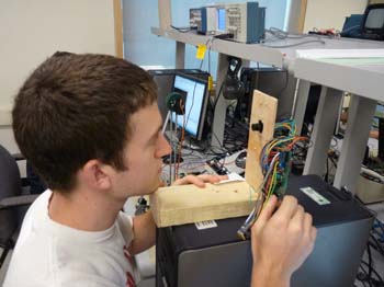
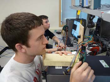
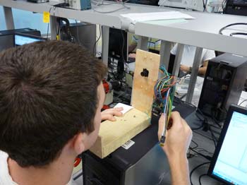
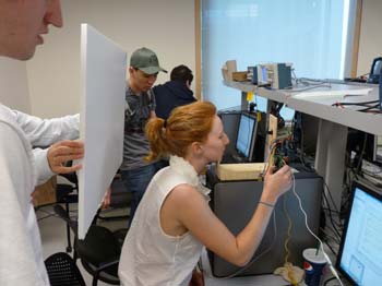
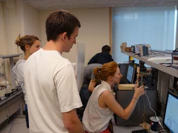
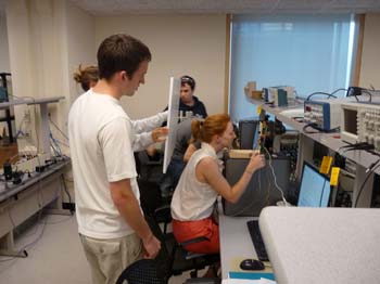
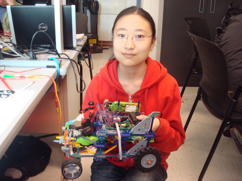
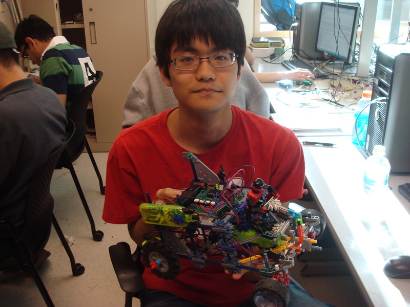
E. Pictures
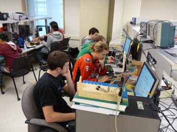
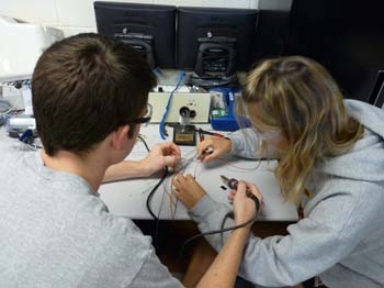
Below are some pictures of us working in the lab. Photos courtesy of Bruce Land.
 |  |  |
 |  |  |
 |  |  |
 |  |
References
This section provides links to external reference documents, code, and websites used throughout the project.
Datasheets
- ATmega644 (8-bit MCU)
- C3088 (Camera Module)
- OV6620 (Image Sensor)
- AT45DB321D (Serial Dataflash)
- LCD (Display)
Reference Code
We referenced preious projects image sensor code to create our camlib.c library.
LED-Following K'NEX Car
Introduction
In a Nutshell
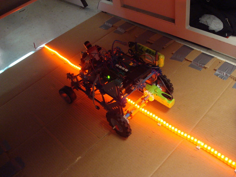
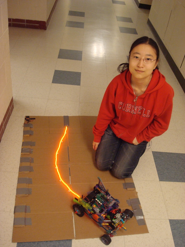
Our ECE 4760 final project was a car made of K'NEX that follows a LED strip.
What We Did
For this project we made a K’NEX car that follows a path made by a LED strip. We used two phototransistors to detect the lights from the LED, while considering ambient light. The voltage generated by the phototransistors were sent to an A-to-D converter so that we could calculate the car’s relative position compared to the LED strip and decide when to turn in software. We then controlled the car by sending the appropriate signals to the motors.
Why We Did It
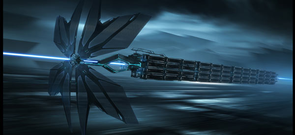
The initial inspiration for this project came from the movie TRON: Legacy. In the movie, there are trains called "Solar Sailers" whose destinations are directed by a beam of light. Here is an image of a solar sailer:
After some brainstorming, we came up with the idea of a car that could drive by itself by following a path of light. We thought this could be a practical and cool project. We initially envisioned the road to be made of two LED paths: one on the left and one on the right of the car. This would be like the lane markers on a road that we see today. A transportation system like this has several benefits:
For example, LEDs consume much less power than lightbulbs. Therefore, we can save power by switching to LED lit roads from regular streetlamps. We an also implement traffic systems by having multicolor LEDs. Green LEDs mean the car can go at the speed limit. Red LEDs mean the car will stop. The lights can change to yellow to make the car slow down. The lights can dynamically change so that a certain distance before and after a car is yellow. This could prevent bumper-to-bumper accidents. This system can also combat drunk driving and other traffic accidents, since the driver is no longer a human.
High Level Design
Background Math
For our project, we used an Emitter-Follower (or Common Collecter) setup for the phototransistors. We desired a circuit that generated an output that "moves from the low state to a high state when light is detected." When light was not detected, we wanted the ADC to output a lower number, and a higher number when light was detected. The emitter-follower circuit will output approximately Vout=Ie*Re, where Re is the emitter resistor and Ie is the emitter current.
Logical Structure
Our hardware logic structure looks as follows:
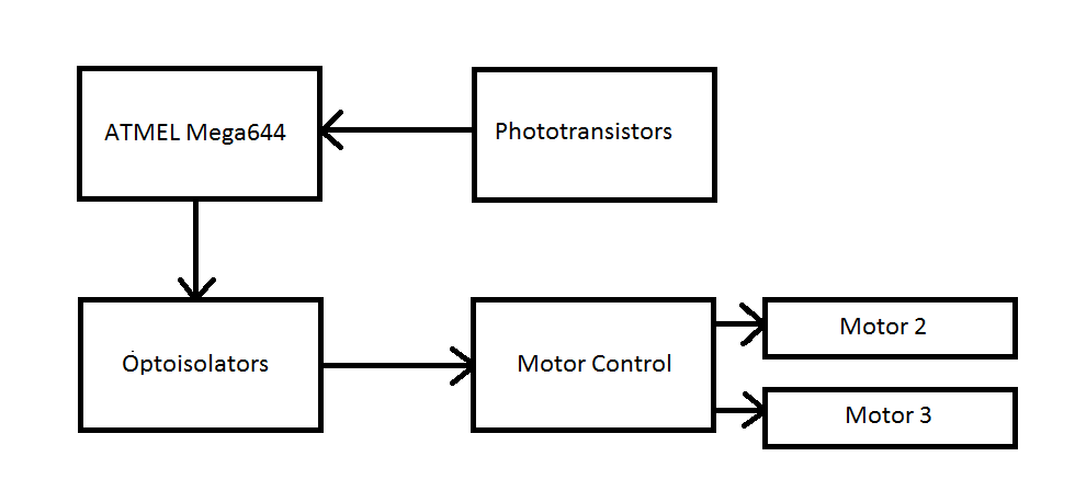
In our project, the phototransistors sent their outputs to the ATMEL Mega644 microcontroller. The MCU then calculates which motors should move based on the phototransistors and sends a signal to the optoisolators telling which motors to turn on. Depending on which optoisolator is turned on, the motor control will tell which motor to move. We used optoisolators to separate the MCU from the motor circuitry. Optoisolators isolate the LED side of the circuit from the phototransistor side of the circuit, ideally protecting the MCU from any unknown outputs from the motor controller.
Hardware/software Tradeoffs
Snce we used K'NEX to build our car, we had to deal with an imperfect steering system. This steering system had a very limited turning angle. However, since the parts were preowned, it was free, as opposed to buying a toy car.
Another tradeoff we had to make was the LED strip color and photodetector. In our project description, we talked about how we wanted green LEDs to mean go and red LEDs to mean stop. We found that multicolor LEDs were more expensive than single color LED strips. We also had trouble finding LED strips that were sideways flexible, long, and cheap. We did not want orange LEDs, but orange LEDs were the cheapest available option. Additionally, there were phototransistors in stock that were sensitive to the dominant wavelength of the LED strip. Therefore, we chose the orange LED strip.
Standards
We used USART to communicate with PuTTY when debugging our project. However, we took it out in the final stages, after it was no longer necessary.
Patents, Copyrights, Trademarks
K'NEX is a trademark of K'NEX LP Group.
Hardware Design
K'NEX Car Design
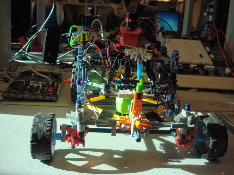
We wanted to make a car out of K'NEX because we owned a lot of K'NEX that we could use for free in our project. The K'NEX car motors and motor controller came from the Cyber K'NEX Ultra 2.0 Robot Kit which goes for $350 on Amazon at the time of this report. This is because the set is no longer sold. Therefore, reproducing our project is probably not viable. Also, we customly built our K'NEX car, meaning there is no instruction set for the car. However, if one has the correct parts, it is probably possible to rebuild the car from the pictures.
Motor Circuitry
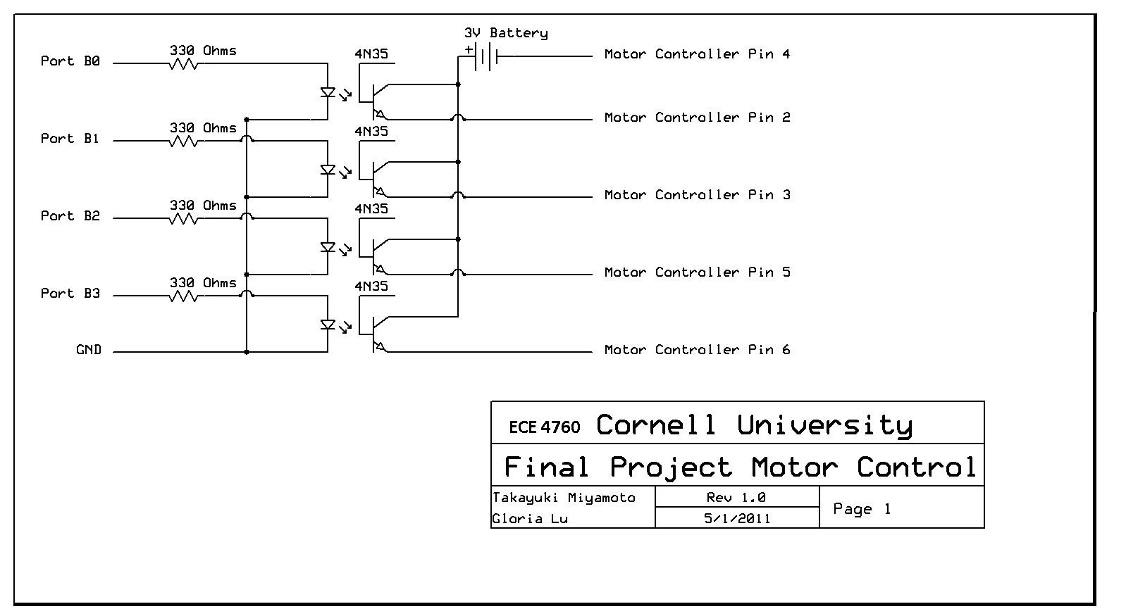
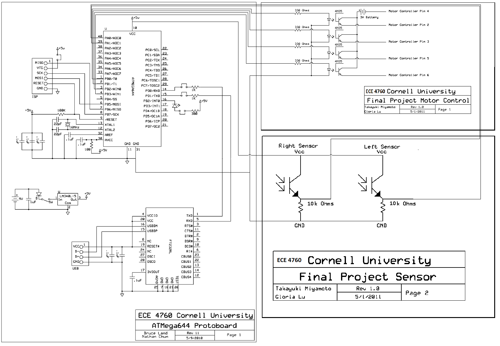
Our project used two motors, which were encased in a K'NEX fitting and were connected to a motor controller (also from K'NEX). Since the motors were from a set that had three motors, the motors are numbered on the K'NEX fitting. We used motors 2 and 3, because they are connected to the same controller (motor 1 has its own controller). The motor controller had 6-pin port which one could use to drive the motors. This is because the K'NEX set has a parent controller that sends instructions to the motor controller through these pins. We experimented with low voltages to see how we could interact with the pins to make the motors turn. The following diagram shows the pin diagram of the motor controller:
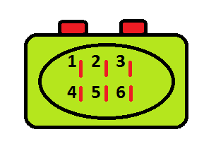
The following table maps the motor control pins to their function:
| Motor Cotroller Pin # | Voltage Required (V) | Function |
|---|---|---|
| 1 | Unknown | Unknown |
| 2 | 3 | Turn Motor 3 Clockwise |
| 3 | 3 | Turn Motor 3 Counter-Clockwise |
| 4 | 0 | Ground |
| 5 | 3 | Turn Motor 2 Counter-clockwise |
| 6 | 3 | Turn Motor 2 Clockwise |
To tell if a motor is spinning clockwise or counter-clockwise, we put the wire on the left side and position the motor casing so that we can read the number on it.
Our initial tests found that Pin 1 is ground, and a voltage of -1.5V was required on Pin 4 for the motors to turn in the opposite direction. However, when we raised the pin voltages to 3, we found that we did not need Pin 1 to drive the motors. Thus, we left Pin 1 empty, since we were able to control the motors fine using only pins 2-6.
The circuitry for the motor control is in the appendix. We measured the resistance of the motor controllers and it turned out to be around 47kOhms. To be safe, we used an optoisolator (4N35) to separate the microcontroller from the motor controller. We used 330Ohm resistors in series with the input of the optoisolator to prevent the microcontroller side of the circuit from shorting when the internal LED was on. The actual resistor values were 331Ohms, 328Ohms, 326Ohms, and 324Ohms. We drove the optoisolators from Port B0 to B3 on the microcontroller. If we put an active high on the port, the motor would spin.
On the motor control side of the optoisolator, we connected the collecter to a 3V battery source and the emitter of each optoisolator to the motor control pin. We did not bias the base, because the light from the internal LED was enough to drive the optoisolator.
Motor 2 controls the front steering wheels and motor 3 controls the back driving wheels.
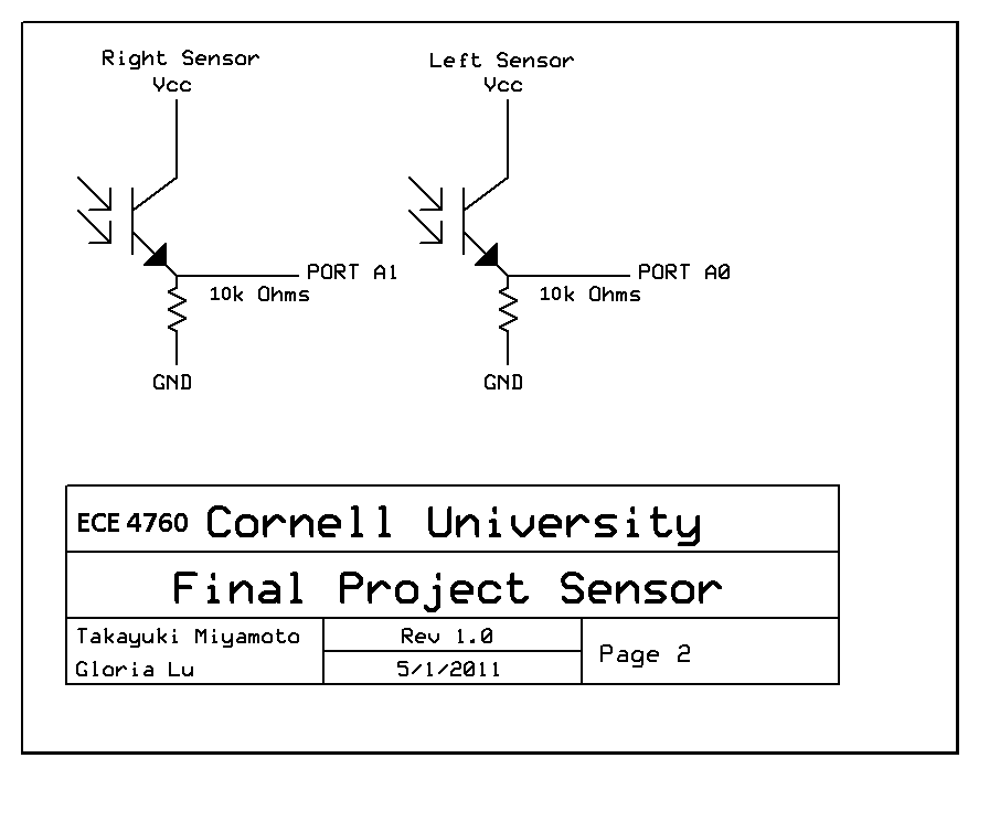
Sensor Circuitry
The circuitry for the phototransistor is in the appendix. We got two phototransistors that were sensitive around the 615nm wavelength our LED strip was emitting. We used an emitter-follower setup to amplify the current that was produed by the phototransistor when it was turned on. The datasheet stated that the current when turned off was around 0.5 microAmps at most, and when turned on, would range between 0.25 to 0.6mA at Vce=5V. Since our MCU Vcc is 5V, we could simply use the numbers from the datasheet. The ADC reference voltage was set to 2.56V, so we had to find a resistor that was between 4266.6 to 10240 Ohms. We tried a resistor of 10kOhms, which worked well so we decided to stick with it. The actual resistor values were 10.2kOhms and 9.86kOhms. We connected the output of the emitter-followers to Port A0 and A1 so that we can use the ADC on the MCU.
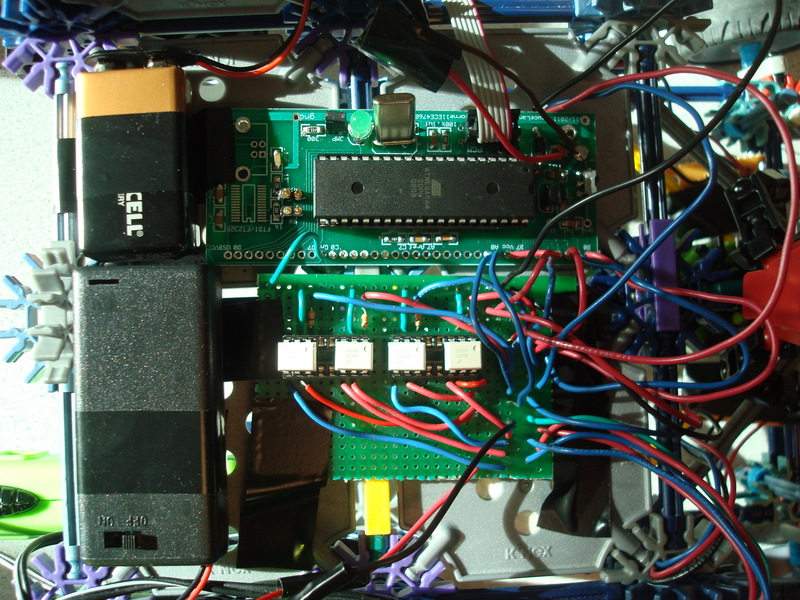
Microcontroller
Since our project was a car, we could not use the STK500 for our final design. However, we left out the MAX233 and RS232 because we did not need a serial interface on our final board. This posed some difficulties in debugging in the later phases, but saved money, since our final design did not need a serial interface.
We used an ATMEL Mega644 with a 16MHz crystal because this is what we used throughout the semester. Although we probably could have used a less-powerful MCU, we decided to stick with what we knew best.
For the project, we used ports A0 and A1 for analog inputs from the phototransistor circuit. We used ports B0 to B3 to control the motors, and port D2 to control the test LED on the custom PC board.
Test track
We made our test track using the LED strip and some cardboard boxes we had lying around in our dorm. We flattened the cardboard and put the LED strip in the center. To make sure that we can still configure the track in different paths, we only tied down one end of the LED strip. This side was attached to a 9V battery. Even though the LED strip required a 12V source, 9V was enough to light the LEDs, so we used one 9V battery.
Software Design
Our software consisted of test components and the final design. We started off with code to turn the motors after we figured out how the K'NEX motors worked. This test code spun the two motors in two different directions. We used PORT B to do this, since PORT A was reserved for the ADC necessary for the phototransistors. We used C macros to keep track of which port was assigned to which motor/direction.
Once we got the motors working, we switched over to the phototransistors. After we got the hardware prepared, we put one output of the phototransistor into PORT A0 and the other into PORT A1. We initiallized the ADC like we did in lab 3 for the trimpot controller . To test if the phototransistors worked, we used uart.c and uart.h to communicate with PuTTY. We printed out the ADC output from one phototransistor, and then the other. Since the conversions take time, we found that in order to do two conversions, we needed to wait several cycles between reading and starting the conversions. Therefore, we created a task adc() which runs every 10ms to read one output (so it takes 20ms to read both). This was more than enough time to read the outputs and since our car was not very fast, we did not ned to sample the phototransistors any faster.
One thing we needed to take care of was to make sure the ADC did not respond to ambient light. Since the phototransistors were underneath the car, ambient light did not pose a large problem. Underneath our car, the phototransistors only outputted between 3 and 10 when the LED was turned off. When the lights were turned on, it detected between 3 and 230, depending on where the LED strip was. If the phototransistor was only detecting 3, it meant that the LED strip went out of the phototransistor's detection range (which falls after around >30 degrees). To kill ambient noise, we set a threshold so that if the output of the ADC was less than the threshold, the software did nothing with the motors. This threshold was set to 20, since it was signifcantly greater than 10 and it worked well.
The greatest challenge was putting the two parts of our hardware together in software. First, we made a simple test program that would spin only one motor in only one direction. By doing so, we were able to test whether or not the phototransistors and the motors were still working properly. This test was important, because we decided not to add a USB connection to our custom PC board to save money. Thus, once our hardware was soldered together and placed on the car, we could no longer communicate through PuTTY for easier debugging.
While testing our car, we noticed that the motors did not have enough power from the batteries to spin two motors at a time. To get around this, we made our software such that only one motor could spin at any given time. We first checked if the value in Ain0 or Ain1 were greater than the ambient light threshold. We then took the difference of the two outputs. If the difference was between right_bound and left_bound, then the LED strip was centered with the car. Therefore, we drove the back wheels to go forward. If the difference was greater than right_bound, then we made the car turn its front wheels right. If the difference was less than left_bound, we made the car turn its front wheels left. To make sure the steering motor did not keep spinning (since this would cause our car to break) we limited how long the motor was allowed to spin by using a counter. If the steering motor spun for its limit, we made the car drive the back wheels again. We tried spinning both the steering motor and the driving motors at the same time but it did not work. We also tried alternating between steering and driving, but this failed as well.
Much later in the debugging stage, we replaced the batteries in the K'NEX battery pack and noticed that fresh batteries could spin two motors at the same time.
**DO NOT USE BATTERIES FROM WHEN YOU WERE 10 YEARS OLD!!!**
The fresh batteries spun the motors much faster, so we had to change some of the timings in our code. Additionally, we could now apin both motors at the same time, allowing us some freedom. However, since we already had something that was remotely working, we decided to keep the only-one-motor-at-a-time setup.
One problem that rose with the new batteries was speed. The car motors ran much faster with new batteries. This was fine if the car was going straight, but on turns, the car would drive too fast and it would often go off the LED strip. To fix this, we implemented a simple software Pulse-Width Modulator (PWM) to control the driving wheel speed. If the car was going straight, it would drive at full speed. On turns, we made the car drive at 25% of full speed, meaning the PWM was on for 1/4 of the time. This causes the car to move slowly and to look like it is stuttering. However, we could not drive the motors too slowly because the motor control circuit and the motors react slowly.
Now that we could drive two motors at the same time, we added in a function that would recenter the wheels when the car was coming out of a turn while still driving. This made some turns smoother but also added some limitations on S-shaped tracks because the car would now go straight a tiny bit more before turning in the opposite direction.
Lastly, we made our car recenter its steering wheels and stop driving when the phototransistors detected less than the ambient threshold. If the phototransistors detected less than ambient, it meant that the car was off the LED strip for whatever reason. By recentering the wheels, it allowed us to test our car again without manually centering the wheels. We were able to do this by using the turning limits we used on the wheels mentioned earlier. We simply made the steering counter go back to 0 if it was not at zero. If the counter was less than 0, we made the steering motor turn right. If the counter was greater than 0, we made the steering motor turn left.
Results
Speed of Execution
Overall, our project responded very quickly to the LED strip. The motor state was updated every 25ms, which was fast enough for practical purposes. The PWM made the car slowly on turns, but this slow speed was necessary for the car to turn without overshooting the track.
Accuracy
Our car, due to its design, had a very limited turning range. The phototransistors would detect the light, but if a turn was too sharp, the car would drive off the road, often hooking the LED strip and dragging it. However, for turns within its range, the car would be able to make the turn properly.
Another problem was a straight line. Again, because of it's design, the car would never actually drive perfectly straight. It would always be biased a bit to the left or right. This caused some problems on straight paths, because it would still not drive straight. On straight paths, sometimes, the path is short enough, or the car is straight enough that it would drive fine. However, the car would sometimes oscillate on the straight path.
Safety Enforcement
Our car was relatively safe, since our car was designed to stop if the phototransistors were not detecting above ambient light. This meant that our car would not run into other people or run amok in the classroom. Once the car ran off the track, it would immediately stop. Our car, unfortunately did not have airbags for our driver, but I think he is okay.
Interference with Other People's Designs
Our car had two motors that could have created some noise for other people. However, since our circuit was right over the motors and it was running fine, we highly doubt it was causing problems for others.
We also used an LED strip that emiited orange light, which may have caused problems for other people if they had projects operating on a similar wavelength. If we were to interfere, it was probably the amount of space our car required. The LED strip was 38" long. We were able to test it underneath our workbench, but we may have gotten in the way of other people. Later in testing, we took our project outside the lab room and tested in the hallway.
Usability
Our project is usable, but the limited turning angle may pose a problem. If the LED strip turns too sharply, the car will react, but not be able turn sharply enough. This turning angle is approximately 30 degrees.
Another thing we realized is that the car can catch the LED strip and drag it if it got close enough. To fix this flaw, we would need the LED strip to be embedded into the path so that it is on the same elevation as the road. That way, the car can drive over it easily. We couldn't really do that with this project while keeping the road configurable. One option we had was to take a large sheet of glass (or some other stiff, transparent sheet) and put it over the LED strip. However, this would take time and money to get. According to google, a large sheet of glass goes for at least $100.
Conclusion
Expectations
Our project met our expectations fairly well. After building our K'NEX car, we realized that it would have a limited turning angle. The final design only reinforced this, because our car would go off the LED strip path for sharp turns. However, if the angles were within the car's turning angle, the car would behave as expected.
One thing we did not account for was the height of the LED strip. The LED strips we used in other classes were rounded and low, so our car would be able to go right over it. However, those strips are not designed to bend left and right. Thus, we bought an LED strip that was flexible in the left and right directions. This LED strip ended up being tall and were straight, so the car could not go over the light. Instead, the car would end up grabbing the LED strip and dragging it.
Conform to Applicable Standards
When testing our project, we used USART to handle communication between the computer and the microcontroller. In our final design, to the best of our knowledge, we did not have any standards that we needed to follow.
Ethical Considerations
We followed the IEEE Code of Ethics to the best of our knowledge. Since our project was a moving object, we had to make sure it would not endanger the well-being of the public and environment. We made sure that if the car was not detecting light significantly above the ambient threshold, it would not move. If the car was moving previously, but stopped detecting light, it would stop moving as well. That way, our car was guaranteed to stay within our testing area, which we made sure people would not enter.
The motors were from a K'NEX set that was meant for ages 10+, meaning our car is not suited for children under the age of 10. Our car also has small parts, meaning it poses choking hazard for small children. We made sure there were no small children nearby when working on our project. If our car is to be replicated by some other party, they must make sure to follow the age restrictions.
Our car and LED strip required 9 Volts, which is within safe range. Our components can produce low amounts of heat and magnetic fields, both of which cannot be helped and should be safe. The LED strip should not be stared at for long periods of time, for the light emitted are quite bright. However, there are no health warnings for the LED strip on the vendor website.
All of our claims in this report are honest and realistic. We are quite inexperienced, with this project being the first real ECE design project. We tried our best to do our best while keeping any legal restrictions, ethics, and standards in mind. If our project did not follow any rules, it would be because we were unaware of them, even after our research.
We did not accept any bribery in any form, nor did we bribe others in any form. We tried to learn as much as we could from this lab. We thought of appropriate applications of our project. Modern cars can be very dangerous if misused, so a car that could drive itself could be beneficial to the world. LEDs are much more energy efficient than street lamps, so LED-lit roads would be much more energy efficient. Furthermore, LED-lit roads can be placed on any road, where as street lamps would have to be placed next to roads, requiring more space. If cars could follow LED strips, then people would no longer have to worry about drunk driving or reckless drivers. These cars would also benefit disabled people who cannot drive as well.
We have also considered the limitations of our project. For instance, we have to make sure our project is weather-proof. The LED strip we bought was IP67, which means that it is "Totally protected against dust" and "Protected against the effect of immersion between 15cm and 1m" Ingress Protection However, we have to make sure the lights would not be covered by physical objects such as rocks and snow.
Since we are still inexperienced ECE majors, we are still in the process of learning much about the field. We are working hard to improve our technical competence and will only take on tasks when we are fully qualified. We are willing to take any constructive criticism and will acknowledge and correct any errors we have made. We will also credit all who have contributed to our project.
We will not discriminate based on race, religion, gender, disability, age, or national origin. Our product is for all to use and learn from, as long as they are above the age of 10. Any real-world implementation of our project will be for all groups of people. We will not endanger the physical, mental or social well-being of others and will support all of our colleagues and co-workers.
Legal Considerations
We made sure to follow any legal restrictions we found that applied to our lab. We researched if there were any limitations on using the dominant 615nm wevelength of light that our LED strip emitted. We also researched if there were any restrictions for toy cars, such as maximum toy car speed. We were unable to find any legal restrictions that limited either of these.
The K'NEX pieces we used are for ages 10+ so our project is for ages at least 10+ as well. If we were to scale our project to a real car, we must follow the legal speed limits imposed on streets.
Appendix: Images
Appendix: Code
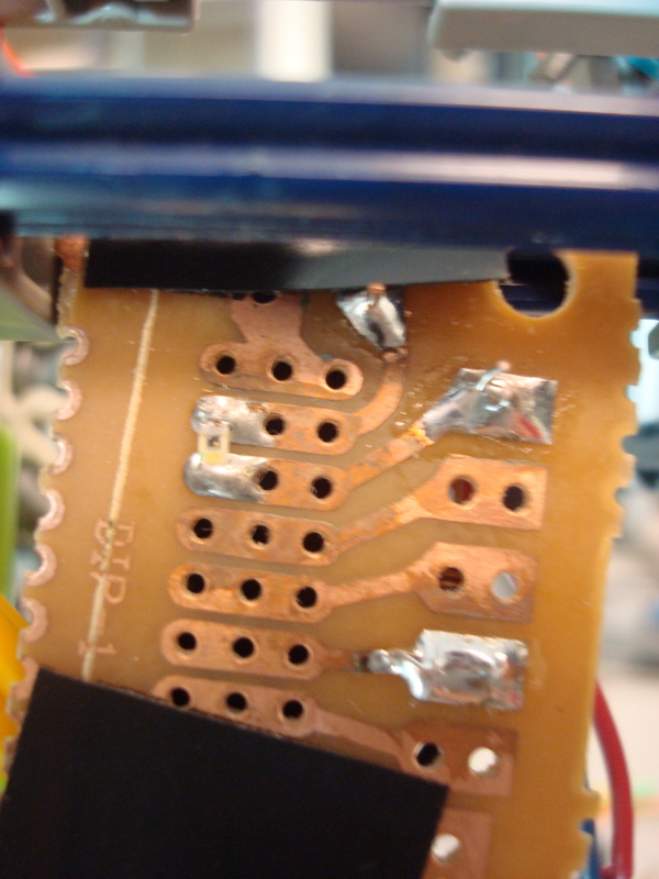
Custom PC Board
Motor Control
Sensor Circuit
Complete Circuit
References
Datasheet
Code/Designs Borrowed
Subscribe to:
Posts (Atom)